- 您现在的位置:买卖IC网 > Sheet目录477 > MICRF500BLQTR (Micrel Inc)TXRX UHF 700-1100MHZ 44-LQFP
MICRF500
Programming
A two-line bus is used to program the circuit; the two lines
being CLKIN and REGIN. The 2-line serial bus interface
allows control over the frequency dividers and the selective
powering up of Tx, Rx and Synthesizer circuit blocks. The
Micrel
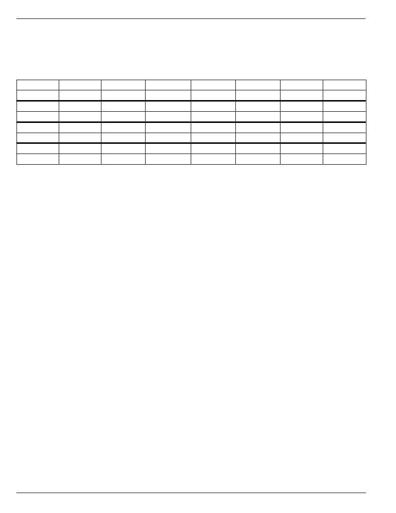
interface consists of an 80-bit programming register. Data is
entered on the REGIN line with the most significant bit first.
The first bit entered is called p1, the last one p80. The bits in
the programming register are arranged as shown in Table 1.
p1 – p6
A1
p59
Pa1
p67
Ref2
p75
OutS1
p7 - p12
A0
p60
Pa0
p68
Ref1
p76
OutS0
p13 – p24
N1
p61
Gc
p69
Ref0
p77
Mod1
p25 – p36
N0
p62
ByLNA
p70
Cpmp1
p78
Mod0
p37 – p46
M1
p63
Ref6
p71
Cpmp0
p79
RT
p47 – p56
M0
p64
Ref5
p72
Fc1
p80
Pu
p57
RxFilt
p65
Ref4
p73
Fc0
—
—
p58
Pa2
p66
Ref3
p74
OutS2
—
—
Table 1. Bit Allocation
MICRF500
14
March 2003
发布紧急采购,3分钟左右您将得到回复。
相关PDF资料
MICRF501BLQ TR
TXRX SGL 300-600MHZ 44-LQFP
MICRF505DEV1
KIT DEV RADIOWIRE 850-950MHZ
MICRF506DEV1
EVAL BOARD EXPERIMENTAL MICRF506
MICRF507YML TR
TXRX FSK LOW PWR W/AMP 32MLF
MICRF600DEV1
KIT DEV RADIOWIRE 902-928MHZ
MK01-C
SENSOR REED SPST-NO SMD
MK01-H
SENSOR REED SPDT-CHANGE SMD
MK02/0-1A66-500W
SENSOR REED SPST-NO
相关代理商/技术参数
MICRF500EVAL1
功能描述:射频开发工具 MICRF500 Evaluation Kit - For experimental use only
RoHS:否 制造商:Taiyo Yuden 产品:Wireless Modules 类型:Wireless Audio 工具用于评估:WYSAAVDX7 频率: 工作电源电压:3.4 V to 5.5 V
MICRF501
制造商:MICREL 制造商全称:Micrel Semiconductor 功能描述:300MHz to 600MHz RadioWire⑩ RF Transceiver
MICRF501BLQ
制造商:Rochester Electronics LLC 功能描述:- Bulk 制造商:RF Micro Devices Inc 功能描述:
MICRF501BLQ TR
功能描述:TXRX SGL 300-600MHZ 44-LQFP RoHS:否 类别:RF/IF 和 RFID >> RF 收发器 系列:- 产品培训模块:Lead (SnPb) Finish for COTS
Obsolescence Mitigation Program 标准包装:30 系列:- 频率:4.9GHz ~ 5.9GHz 数据传输率 - 最大:54Mbps 调制或协议:* 应用:* 功率 - 输出:-3dBm 灵敏度:- 电源电压:2.7 V ~ 3.6 V 电流 - 接收:* 电流 - 传输:* 数据接口:PCB,表面贴装 存储容量:- 天线连接器:PCB,表面贴装 工作温度:-25°C ~ 85°C 封装/外壳:68-TQFN 裸露焊盘 包装:管件
MICRF501EVAL1
功能描述:EVAL BOARD EXPERIMENTAL MICRF501 RoHS:否 类别:RF/IF 和 RFID >> RF 评估和开发套件,板 系列:RadioWire® 标准包装:1 系列:- 类型:GPS 接收器 频率:1575MHz 适用于相关产品:- 已供物品:模块 其它名称:SER3796
MICRF505
制造商:MICREL 制造商全称:Micrel Semiconductor 功能描述:868MHz and 915MHz ISM Band Transceiver
MICRF505_07
制造商:MICREL 制造商全称:Micrel Semiconductor 功能描述:850MHz and 950MHz ISM Band Transceiver
MICRF505BML
制造商:Rochester Electronics LLC 功能描述: 制造商:RF Micro Devices Inc 功能描述:
